Introduction
We live in a multi-protocol world and will continue to do so for some time to come. Different protocols will work better in different applications. In this blog post we will first introduce Modbus and PROFIBUS protocols and talk about their key strengths and applications. Then we will end with a comparison between the two. What we will see is that both protocols have their strengths. Even though the applications where they can be used do overlap, the two protocols work best in different applications. Also, they can complement one another in joint applications.
I have not come to bury Modbus or Profibus, nor praise them, but to add some perspective and knowledge.
Introduction to Modbus
Modbus is the “granddaddy” of industrial protocols. It was originally designed back in the mid-1970s by Modicon as a way for linking intelligent devices with PLCs using a simple master/device concept. The word “simple” is a key descriptor for Modbus – and also its biggest strength, considering its ease of implementation and use. It was first a proprietary protocol that only Modicon could use. Then Modicon decided to publish Modbus royalty-free so that anyone could use it. Finally, Modicon made it an open protocol. During the time that it was published, a number of companies started to use it, which created a number of different interpretations and modifications of the original specification. As a result, there are now quite a few different variations of the protocol out in the field.
The specification document is under 100 pages in length, which gives you a pretty good idea of the protocol’s complexity. As a comparison, Profibus’ specification document is thousands of pages long.
The different flavours of Modbus
When you hear the word “Modbus,” it is typically in reference to either one of three related protocols: Modbus ASCII, Modbus RTU, or Modbus TCP/IP:
- Modbus ASCII was the first Modbus and is a serial protocol typically running on either RS-232 or RS-485 physical layer. All devices are polled on demand from the master and there is only one master. The message frame can be up to 252 bytes long and you can have up to 247 addresses. The message frame and function codes are very simple and are shown in Figure 1.
- Modbus RTU is really just a small variation on the Modbus ASCII protocol. The only difference is in the encoding of the data. ASCII encodes the message in ASCII characters, while RTU uses bytes, thus increasing the throughput of the protocol. In general, RTU is more popular, particularly in new installations.
- Modbus TCP/IP was added much later. One simple way of thinking about Modbus TCP/IP is to imagine it as simply encapsulating a Modbus RTU packet into a TCP/IP packet. There is a little bit more to it than that, but this is essentially what Modbus did. As a result of this, Modbus TCP/IP is also very simple to implement. The tradeoff is that because it uses TCP/IP protocol for all messages, it ends up being slow when compared to other Ethernet industrial protocols, but still fast enough for monitoring applications.
- Note: There is another ‘Modbus’ called ‘Modbus Plus’ which was developed by Modicon. This protocol was never made public and is no longer being used in new applications.
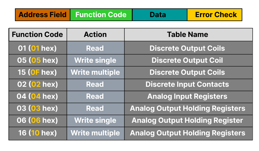
Figure 1: Modbus ASCII message frame and function codes
How Modbus Works
As already stated, Modbus is a simple master-device protocol. The master has full control of communications on the bus, whereas a device will only talk when spoken to. The master will write down outputs and read in inputs from each of its devices every cycle as show in Figure 2.
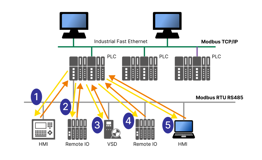
Figure 2: Modbus master/device protocol illustrated
The protocol is pretty basic and therefore there is no additional requirement for the device or master to have a watchdog timer which monitors that communication occurs within a certain time. The devices do not “join” the network. They simply answer whenever a master talks to them. If the master never talks to them, then they simply sit there and wait.
There is also no requirement for diagnostics regarding the device’s health. If the master requests data that does not make sense to the device, then the device can send an exception response. However, if the process variable is bad or if the device is having problems working, there is nothing in the protocol that requires the device to report this. Also there is no standard way for the device to report this.
The Physical Layer:
Modbus ASCII and RTU both typically use either RS-232 or RS-485 physical layer. However, other physical layers such as phone lines or wireless are also used.
Recommend Standard 232 and 485 were established physical layers when Modbus was first developed. RS-232 is for point-to-point, while RS-485 is for multi-drop applications. In both cases, Modbus did not add any new requirements to these physical layers and just used them directly.
This has worked but has caused a few problems in the case of RS-485. The problem is that the physical layer has a number of variations: 2-wire, 4-wire, use of common and variations in drivers and grounding methods. Anyone who has worked with Modbus on RS-485 from multiple vendors will already know how to overcome all the variations when connecting up two types in a point-to-point configuration. The fun comes when the site is multi-vendor and you have to combine several variations on one cable.
There are a number of standards for both phone lines and for wireless. Modbus has excelled in these applications because of the small number of timing constraints in the protocol. Both phone lines and wireless modems introduce delays in messages. Sometimes these delays are non-linear throughout the message, which can cause real problems for many protocols. However, Modbus either does not have a problem or can be made to work in these applications.
Typical Applications
1. Controller/monitor to a smart device
In this application, you have one smart device that you need to pull data from. This point-to-point application is what Modbus ASCII/RTU was used for quite frequently. The variations in both the protocol and the physical layer are easy to deal with and this is a simple application to get working.
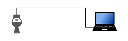
Figure 3: Modbus controller to one smart device
2. Controller/monitor to many smart devices from the same vendor
Like the first application, this is very easy to implement. The variations in the protocol do not tend to be a problem.
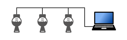
Figure 4: Modbus controller to multiple smart devices
3. Remote monitoring of information from a smart device
Since the Modbus protocol is modem-friendly and has no watchdog timers, implementing remote data collection is very easy.
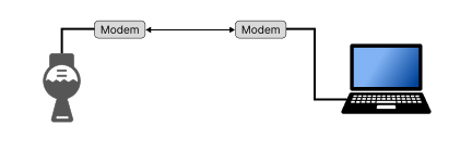
Figure 5: Modbus remote monitoring application
Introduction to Profibus
If Modbus is the “granddaddy” of protocols, then Profibus is the middle aged guy who still works out regularly. Profibus was designed in the 1990s to meet all of your industrial communications needs for both factory and process automation. Like Modbus, there are number of terms that you will hear in reference to this protocol: Profibus DP, Profibus PA, Profisafe, and Profidrive.
One way of figuring how these terms fit together is to think of Profibus like a book with many chapters. The book would be called Profibus DP (Decentralized Peripheral). The book’s chapters would be called: Profibus PA for process automation, Profisafe for safety applications, and Profidrive for high-speed drive applications. Profibus PA, Profisafe, and Profidrive are all part of the Profibus DP protocol.
There is also another protocol called PROFINET. PROFINET is the son of PROFIBUS and is in prime shape. However, this will be a topic of another blog posting.
How does Profibus work?
Profibus is also a master-device type protocol but with an additional token ring protocol to allow for multi-masters to be on the bus. Also, unlike Modbus, all devices go through a start-up sequence where they “join” the network. Each device maintains a failsafe timer where, if the master does not talk to it within a certain time limit, the device will go into a safe state and will require the master to redo the startup sequence before it reenters data exchange. This, in combination with a watchdog timer in the master, ensures that all communications occur every bus cycle within a certain time value.
The general bus scan would happen as shown in Figure 6. Master A receives the token, which gives it control of the bus. It will then do date exchange with each of its devices. When it is done, it will pass on the token to the next master (if there is one).
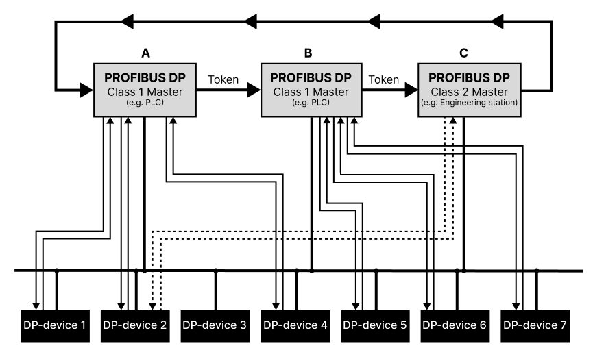
Figure 6: PROFIBUS master/device bus scan
Built into the protocol is also the requirement for detailed diagnostics from each device. Included in this is a method so that during normal data exchange, a device can alert the master that it has diagnostics which the master will then read during the next bus scan.
Physical Layer
The main physical layer for Profibus DP is based on RS-485, the same as Modbus. However, in Profibus’ case, the Profibus specification does not simply refer to the existing RS-485 specification, it extends the RS-485 specification. The physical layer was tightened up so that only two wires are required, and the speed can go as fast as 12 megabits per second. The Profibus specification also standardized on the connectors. This all has a real benefit when working with multiple vendors – wiring is easy and the same.
For instrumentation, Profibus also has another physical layer called IEC 61158-2, Manchester Encoded, bus-powered, intrinsically safe (MBP-IS). This physical layer provides power and communications on the same two wires. The intrinsically safe concept has a big advantage on installation costs. Working with hazardous environments, there are two approaches: you can contain the power going to the instrument in the hazardous area or you can limit the power going out into the hazardous area. The containment method is the traditional method and the one required for RS-485. It uses metal conduit and seals to “contain” the energy. Both the conduit and seals are expensive to buy and install. The second approach of limiting the power going to the field is called intrinsically safe. With it, you do not need conduits or seals (except maybe at the starting cabinet). The cost saving are significant.
Profibus noise immunity
Both of Profibus’ main physical layers (modified RS-485 and MBP-IS) are highly detailed physical layers and have had the major benefit of excellent noise immunity. This has been proven over and over again at countless sites. Once Profibus is designed and installed properly, it is next to bulletproof.
Standardized outputs and function block design
For instrumentation, Profibus has a part of its standard called the profile standard, which is a standardization of an instrument from the bus’ point of view. It defines not only standard inputs and outputs, but also functions and functionalities from within the instrument. This helps in both the setup and integration of field instruments and allows for easy multi-vendor applications.
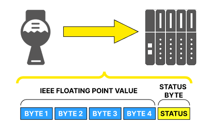
Figure 7: PROFIBUS function block design
For example, the output from all Profibus PA transmitters is five bytes long. The first four bytes are the IEEE floating point value of the process variable. The fifth byte is the status byte that tells if you can trust the process variable. The major status codes are all standardized in the specification so you will know that, for example, if you get a value of x80, then everything is okay. This applies to all transmitters from all manufacturers.
Typical applications
Profibus was really designed to automate your entire plant. It does not matter the size of the plant or if it is factory automation, which is mainly made up of discrete input/output, or process automation, which is mainly made up of analog input/output. Profibus can handle it well.
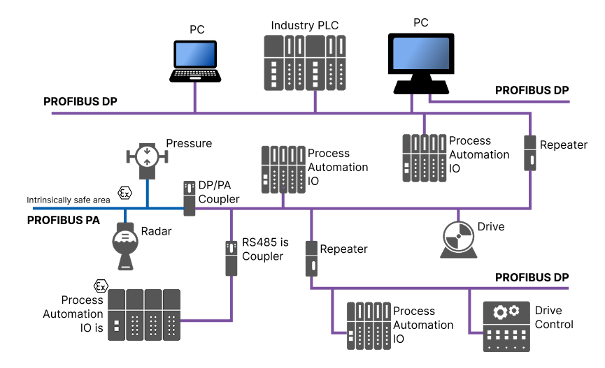
Figure 8: PROFIBUS automation application
Comparison:
In the chart below, let’s review the comparison of Profibus and Modbus based on the factors we have discussed.
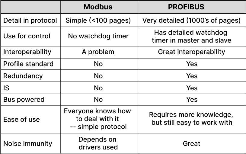
Figure 9: Modbus/PROFIBUS comparison chart
Combined application:
One application gaining in popularity offers the best of both worlds. This application uses Modbus as a data transport between a master controller and data concentrator or remote station. One example of this sort of application is shown in figure 10, where you have a small PLC polling data from some radar units using Profibus, and then passing the information up to the control system using Modbus.
The benefits of this type of setup are significant.
On the Modbus side:
- Easy modem support
- Simple implementation
On the Profibus side:
- The standardized output and diagnostics from the instruments
- Robust physical layer
- Intrinsically safe installation, which reduces installation costs
- Ability to communicate to the field instruments over the bus
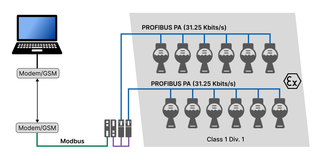
Figure 10: Combined Modbus/PROFIBUS application
Conclusion:
Modbus is a very simple protocol that is easy to use and modem friendly. However, it has a fair amount of variation in the protocol itself and in its physical layer definition, which creates problems in multi-vendor applications.
Profibus is a very robust protocol that was designed to automate entire plants. It works extremely well in multi-vendor applications and has detailed diagnostics. However, the timing requirements create some challenges when used with modems.
When looking at connecting a controller to one smart device in a point-to-point configuration, then Modbus is a pretty easy way to go. If a modem is involved, here again Modbus is hard to beat.
As soon as the point count starts to increase, if different vendors are involved, or if it is a hazardous environment, then Profibus is a better solution.
Did you know??
JCOM Automation Inc. sells:
- Modbus remote I/O racks? Click here
- PROFIBUS I/O racks? Click here
- Both Modbus and PROFIBUS training? Click here